Hi, We installed NSX-T in the previous post, before we can add other NSX-T in the cluster, we need to add compute manager into the NSX-T manager.
1- Login to the NSX-T portal
https://NSX-T_IP_Address
2- go to the System –> Fabric –> Compute Manager –> Add Compute Manager
3- Enter vCenter information
Note: The options “Create Service Account” and “Enable Trust” is required when you would like to prepare an NSX-T Cluster with vSphere Lifecycle Manager.
Hi, I want to start installing and configuring NSX in my environment today.
There is a question How can I build a Nested laboratory?
For my nested lab, I used the below physical devices:
1- 1 * ProLiant DL Gen9
2- 1 * Cisco Switch
3- 1 * Firewall
Physical Network Design:
Physical = Firewall to Cisco Switch = Trunk
Physical = Cisco Switch to ProLiant DL Gen9 = Trunk
VDS = 2 * UPLINK to Physical NICs (PNIC)
Port Group on the standard switch or VDS ESXi host on ProLiant DL Gen9
LAB-MGMT-VLAN-PG = We used for MGMT VMS like DC, vCenter, NSX MGR
LAB-MGMT-Trunk-PG = ESXi MGMT
LAB-SW-TOR-Trunk = We used to connect Virtual Router Cisco to ESXi
LAB-VLAN-To-Firewall = We used to connect Virtual Router Cisco to Firewall
Note: You can have more port groups for other purposes like VSAN, vMotion, and…
IP and VLAN Design
Install Management Services on Physical Server
DC
I need to install a DC as a Domain Controller and DNS server. I install khoshraftar.com, and I used the LAB-MGMT-VLAN-PG port group to connect my DC to the network. I define all A records that we need for our services link vCenter, ESXi, NSX manager, and…
vCenter
Furthermore, I need to install a vCenter server. I used the LAB-MGMT-VLAN-PG port group to connect my vCenter to the network. I created a Datacenter and 2 clusters (cluster Compute and MGMT).
I created a VDS switch and These below port groups.
LAB-MGMT-Trunk-PG = We used for MGMT ESXi
Edge-Transport-overlay-vtep-Trunk = We used for NSX-Edge VMs
Edge-uplink2-Trunk = We used it for NSX-Edge VMs
Edge-uplink3-Trunk = We used it for NSX-Edge VMs
ESXi
Likewise, I need to install ESXi as a nested hypervisor. Each ESXi host has 3 network cards.
Network Card1 = LAB-MGMT-Trunk-PG
Network Card2 = LAB-SW-TOR-Trunk
Network Card3 = LAB-SW-TOR-Trunk
Note1: I configured VLAN Mgmt in ESXi VAMI –> System Customization –> Configure Management Network –> VLAN.
Note2: I Enable Promiscuous Mode on all port groups.
NSX Manager
I install NSX Manager and connect to the LAB-MGMT-VLAN-PG port group.
Move the virtual machine to another location using stretched NSX objects
NSX FEDERATION OVERVIEW
With NSX Federation, you can manage multiple NSX-T Data Center environments with a single pane of glass view, create gateways and segments that span one or more locations, and configure and enforce firewall rules consistently across locations.
To start using NSX Federation, you must first install Global Manager and then add different NSX-T instances as locations. The NSX-T manager appliances that are managed by Global Manager are called Local Managers. Once the locations are configured, you can configure networking and security from Global Manager.
It is recommended to have active and standby Global Manager clusters in different locations for resiliency and availability.
NSX FEDERATION ENDPOINTS
In an NSX Federation environment, there are two types of tunnel endpoints.
Tunnel End Point (TEP): the IP address of a transport node (Edge node or Host) used for Geneve encapsulation within a location.
Remote Tunnel End Points (RTEP): the IP address of a transport node (Edge node only) used for Geneve encapsulation across locations.
You will be creating RTEPs on Edge Nodes during the lab.
LAB ARCHITECTURE
Click to enlarge
The lab environment consists of a multi-site deployment. Each site is managed by an independent vCenter and NSX Manager. At Site A, a single NSX Global Manager has been pre-deployed to allow for the creation of the federation setup as part of the lab exercise. The workload clusters at each site have been prepared for NSX-T already, and two Edge nodes per site have been grouped in an NSX Edge Cluster. At Site A, the HOL Multi-Tier WebApp is functional, and its VMs are connected to VLAN-Backed vDS port-groups. The physical network is simulated using a single Linux Router VM named vPod Router running Quagga. The vPod router will act as the ToR switches at both sites.
The vPod router acts as the default gateway for any management or infrastructure network at both sites. The vPod router also acts as the default gateway for the three WebApp networks (Web, App, and Db). The vPod router is running BGP with AS 65100, and it is already configured to peer with the NSX infrastructure on 4 different VLANs: 100 and 200 at SiteA, 300 and 400 at SiteB.
In this lab, you are going to start by onboarding the NSX Managers at each site to the Global manager. After this step, any configuration, global or local to a specific Local Manager can be accomplished through the Global Manager UI. Next, you will configure the edge clusters at each site to forward RTEP traffic between the two locations. RTEP interfaces must be configured on each edge node on a different subnet and VLAN than the one in use for the TEP traffic. IP Pools for the RTEP interfaces have been pre-created in the lab and routing between the RTEP subnets at each site set up in advance.
Once the NSX Federation is set up, the first logical component you are going to create is a stretched Tier-0 Gateway. The stretched Tier-0 Gateway will have SR components deployed on four edge nodes, two at SiteA and two at SiteB. Extending the design recommendations for a single site, you will configure the SR component on each edge node to peer to the physical network over two distinct VLANs. You will use VLAN 100 and 200 at Site A, and VLAN 300 and 400 at Site B. In the lab, however, you will only configure a single BGP peering per site: Edge-01a to the vPod Router over VLAN 100, and Edge-01b to the vPod Router over VLAN 300 to save time and focus on federation-specific configurations.
After creating a Tier-0 Gateway, you are going to configure a Stretched Tier-1 Gateway and Stretched segments for the WebApp. You will advertise connected segments at both sites.
After configuring Stretched segments and Global security policies, you will migrate web-01a VM to Site B to verify that the Global security policies are still effective after the migration.
You will also explore the local egress functionality of NSX Federation.
Activate Global Manager
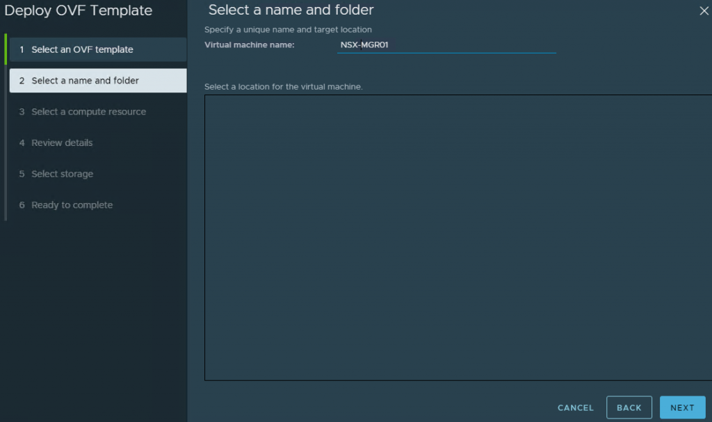
A Global Manager must be deployed for NSX Federation. Deploying a Global Manager appliance is similar to deploying an NSX Manager appliance. The main difference is that during the deployment, you must select “NSX Global Manager” as the role for the appliance. The appliance size must be at least Medium or Large; it cannot be small for Global Manager.
The appliance has been deployed already for you in this environment so let’s activate the Global Manager.
Expand the RegionA bookmark folder
Select NSX Global Manager
Click LOGIN
Go to System
Click LOCATION MANAGER
Click MAKE ACTIVE
Click the Global Manager Name field
Type GM
Click SAVE
Verify that the Global Manager shows as Active.
Add Site A Location
Now that the Global Manager is active, you must add locations to start managing local NSX-T instances. Let’s first add a NSX Manager in Region A as a location. NSX Manager instance added as a location is also referred to as a Local Manager.
Scroll down
Click ADD ON-PREM LOCATION
Click Location Name field
Type Site-A
Click FQDN/IP field to provide the FQDN/IP address of the NSX Manager in Region A
Type 192.168.110.15
Leave the auto-filled username and password for the NSX Manager.
To retrieve the SHA-256 Thumbprint, you can SSH into the NSX Manager appliance or simply use the NSX-T UI. Let’s use the NSX-T UI for this one.
Open a new tab in the browser
Expand the RegionA bookmark folder
Select NSX Manager GUI
LOG IN
Go to System
Click Appliances
Scroll down to view more details about the appliance
Click VIEW DETAILS under 192.168.110.42
Click Copy to clipboard icon next to CERT THUMBPRINT to get the SHA-256 Thumbprint
Now that you have the thumbprint, let’s go back to the Global Manager to finish adding the NSX Manager as a location.
Use the first NSX tab in the browser to go back to the Global Manager
Right-click the SHA-256 Thumbprint field
Click Paste to paste the thumbprint
Click CHECK COMPATIBILITY to make sure the current NSX Version is compatible
Click SAVE to finish
Now, you can see that the Site A has been added as a location.
It may take a while for the Sync Status to show as success.
Scroll down to view the location that has been added
Refresh the Sync Status and verify that the Sync Status is now shown as Success
There is a blue notification banner that asks if you want to import objects and policies found in the Local Manager. If you import your configurations from the Local Manager to the Global Manager, the Global Manager will start managing those objects and you cannot edit those objects from the Local Manager any longer.
For more information about requirements and configurations that can be imported to the Global Manager, refer to the official VMware documentation here.
For this lab, you are not going to import any objects.
Click No, thanks on the blue notification banner.
Add Site B Location
Let’s add a NSX Manager in Region B as another location in the Global Manager.
Click ADD ON-PREM LOCATION
Click Location Name field
Type Site-B
Click FQDN/IP field to provide the FQDN/IP address of the NSX Manager in Region B
Type 192.168.210.15
Leave the auto-filled username and password for the NSX Manager.
This time, let’s use the NSX Manager CLI command to retrieve the SHA-256 instead of using the NSX-T UI.
Open a PuTTY session by clicking on PuTTY icon in the task bar
Scroll down through the Saved Sessions to find a session called nsxmgr-01b.corp.local
Select nsxmgr-01b.corp.local
Click Open
Type the CLI command get certificate api thumbprint and enter
Right-click the thumbprint to copy it to the clipboard
Close the PuTTY session by clicking the X in the top right corner
Click OK to close the session
Now that you have the thumbprint, let’s finish adding the NSX Manager as a location.
Right-click the SHA-256 Thumbprint field
Click Paste to paste the thumbprint
Click CHECK COMPATIBILITY to make sure the current NSX Version supports NSX Federation
Click SAVE to finish
Scroll down to view the Local Manager for Site B that has been added
Now, you can see that the Site B has been added as a location.
It may take a while for the Sync Status to show as success.
Refresh the Sync Status and verify that the Sync Status is now shown as Success
Click No, thanks on the blue notification banner asking if you want to import your configurations from the Local Manager in Site B
Add RTEPs to Edge Cluster in Site A
You must configure a remote tunnel endpoint (RTEP) on Edge nodes in each location if you want to create stretched gateways and segments that handle the cross-location traffic. You must configure an RTEP in all the Edge nodes within an Edge cluster. Remember that TEP and RTEP must use different VLANs and layer 3 subnets.
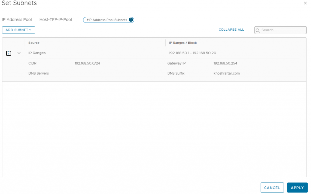
The RTEP IP pool for Site A has already been created. Let’s configure RTEPs for the Edge cluster at Site A.
Scroll up to view both locations in one view
For Site-A, click NETWORKING
Click CONFIGURE to start configuring sitea-edge-cluster
Click SELECT ALL to check both edges (edge-01a and edge-02a)
Expand the Select Edge Switch dropdown list
Select nvds
Click the RTEP VLAN field
Type 135
Expand the Select IP Pool dropdown list
Select SITEA-RTEPS-POOL
Click SAVE
The green notification banner shows that all the Edge nodes in the sitea-edge-cluster have been configured successfully.
Add RTEPs to Edge Cluster in Site B
Again, RTEPs must be configured in Edge clusters in both locations. The RTEP IP pool for Site B has already been created for you. Let’s configure RTEPS for the Edge cluster at Site B.
Expand the menu at the top to go back to the Global Manager
Select GM
Go to System
Go to Location Manager
Scroll down to view the Locations
Click NETWORKING for Site-B
Click CONFIGURE to start configuring siteb-edge-cluster
Click SELECT ALL to check both edges (edge-01b and edge-02b)
Expand the Select Edge Switch dropdown list
Select nvds
Click the RTEP VLAN field
Type 235
Expand the Select IP Pool dropdown list
Select SITEB-RTEPS-POOL
Click SAVE
The green notification banner shows that all the Edge nodes in the siteb-edge-cluster have been configured successfully.
Verify RTEPs Configuration
Let’s verify that RTEPs have been configured correctly by looking at edge-01a.
Open a PuTTY session by clicking on PuTTY icon in the task bar
Select edge-01a
Click Open
Maximize the window for a better view
Run the command get rteps and hit enter to see that one RTEP interface has been created for the Edge node and the IP has been allocated from the 192.168.135.0/24 range
Run the command get vteps and hit enter to see the two TEP interfaces with IP addresses from a different subnet than the one for RTEPs, 192.168.130.0/24
Run the command get logical-switches and hit enter to view the automatically generated VLAN logical switch on VLAN 135 for the RTEP traffic (the other two segments on VLAN 130 are for TEP traffic)
Run the command get logical-routers and hit enter to view the automatically created logical router for RTEP traffic, which you can identify by looking for the value RTEP_TUNNEL in the Type column
Closethe PuTTY session by clicking the X on the top right-hand corner
Click OK to close the session
Create a Stretched Tier-0 Gateway
With RTEPs now configured on the Edge nodes, you can create stretched logical components across the two locations to handle cross-location traffic.
You will start by creating a stretched Tier-0 Gateway. At each location, this Tier-0 Gateway will have SR components on each edge node to peer with the physical network over two different VLANs. In Site A, the Tier-0 Gateway will use VLAN 100 and 200 while in Site B, it will use VLAN 300 and 400.
In this lab, however, you will only configure a single BGP peering per site in the interest of time. In Site A, you will create a BGP peering using Edge-01a over VLAN 100. In Site B, you will create a BGP peering using Edge-01b over VLAN 300.
Let’s create a VLAN segment to use for BGP peering in Site A.
Expand the menu at the top
Select GM Global Manager to go back
Close the Local Manager UI tab from earlier by clicking X on the second browser tab
Go to Networking
Click Segments under the Connectivity section
Click ADD SEGMENT
Click the Segment Name field to start giving a name
Type sitea-edge-uplink-1
Expand the Select Location dropdown list
Select Site-A
Expand the Select Transport Zone dropdown list
Select VLAN-EDGE-SITEA-TZ
Scroll down to configure more details
Click the VLAN field
Type 100 and enter
Expand the Select Uplink Teaming Policy dropdown list
Select uplink-1-only
Scroll down further
Click SAVE
There is no need for additional configuration of the segment so click NO
Let’s now create another VLAN segment to use for BGP peering in Site B.
Click ADD SEGMENT
Click the Segment Name field to start giving a name
Type siteb-edge-uplink-1
Expand the Select Location dropdown list
Select Site-B
Expand the Select Transport Zone dropdown list
Select VLAN-EDGE-SITEB-TZ
Scroll down to configure more details
Click the VLAN field
Type 300 and enter
Expand the Select Uplink Teaming Policy dropdown list
Select uplink-1-only
Scroll down further
Click SAVE
There is no need for additional configuration of the segment so click NO
Now, you are ready to create a stretched Tier-0 Gateway.
Go to Tier-0 Gateways under the Connectivity section
Click ADD TIER-0 GATEWAY
Click the Enter Name field
Type Global-T0
Expand the Select Location dropdown list
Select Site-A
Expand the Select Edge Cluster dropdown list
Select sitea-edge-cluster
Click ADD LOCATION to add Site B
Expand the Select Location dropdown list
Select Site-B
Expand the Select Edge Cluster dropdown list
Select siteb-edge-cluster
Scroll down until you see the SAVE button
Click SAVE
The stretched Tier-0 Gateway has been created successfully. Let’s now configure the external interfaces to leverage for the BGP peering on this Tier-0 Gateway. You will start by adding an interface for Site A.
Click YES to continue configuring the Tier-0 Gateway
Scroll down to view additional configuration options
Expand the INTERFACES section
Click SET next to Interfaces
Click ADD INTERFACE
Click the Enter Name field
Type vl100-edge01a
Expand the Location dropdown list
Select Site-A
Click the IP Address field
Type 192.168.254.13/29 and enter
Expand the Segment dropdown list
Select sitea-edge-uplink-1
Expand the Select Edge Node dropdown list
Select edge-01a
Expand the URPF Mode field
Set it to None (this is done because we have Edges in ECMP mode)
Scroll down
Click SAVE
Let’s now create an interface for Site B.
Click ADD INTERFACE
Click the Enter Name field
Type vl300-edge01b
Expand the Location dropdown list
Select Site-B
Click the IP Address field
Type 192.168.254.29/29 and enter
Expand the Segment dropdown list
Select siteb-edge-uplink-1
Expand the Select Edge Node dropdown list
Select edge-01b
Expand the URPF Mode field
Set it to None (this is done because we have Edges in ECMP mode)
Scroll down
Click SAVE
Click CLOSE
With the interfaces configured, you can configure BGP peering. First, let’s configure a BGP neighbor for Site A.
Scroll down to view additional configuration options
Expand the BGP section
Scroll down further to view the BGP configuration options
Click on the Local AS field
Type 65001
Click SAVE
Start configuring BGP Neighbors by clicking Set in the BGP Neighbors section
Click ADD BGP NEIGHBOR
Click the Enter IP field
Type 192.168.254.9
Expand the Location dropdown list
Select Site A
Click the Remote AS number field
Type 65002
Click the Source Addresses field
Select 192.168.254.13
Scroll down
Click SAVE
Let’s now add a BGP neighbor for Site B.
Click ADD BGP NEIGHBOR
Click the Enter IP field
Type 192.168.254.25
Expand the Location dropdown list
Select Site B
Click the Remote AS number field
Type 65002
Click the Source Addresses field
Select 192.168.254.29
Scroll down
Click SAVE
Click CLOSE
The last thing you will configure in this lab on the Tier-0 Gateway is route redistribution. This is in preparation for when you create and connect a stretched Tier-1 Gateway to this Tier-0 Gateway. Tier-0 Gateway will advertise Tier-1 Gateway connected interfaces and segments as well as NAT IPs.
Expand the ROUTE RE-DISTRIBUTION section
Scroll down to view more options
Click Set next to Site-A to configure route redistribution for Site A
Click ADD ROUTE RE-DISTRIBUTION
Click the Name field
Type redistribution1
Click Set under the Route Re-distribution column
Check the box for NAT IP under the Advertised Tier-1 Subnets section
Check the box for Connected Interfaces & Segments under the Advertised Tier-1 Subnets section
Click APPLY
Click ADD
Click APPLY to finish
Click Set next to Site-B to configure route redistribution for Site B
Click ADD ROUTE RE-DISTRIBUTION
Click the Name field
Type redistribution1
Click Set under the Route Re-distribution column
Check the box for NAT IP under the Advertised Tier-1 Subnets section
Check the box for Connected Interfaces & Segments under the Advertised Tier-1 Subnets section
Click APPLY
Click ADD
Click APPLY to finish
Click SAVE to finish configuring the Tier-0 Gateway
Scroll down
Click CLOSE EDITING
The stretched Tier-0 Gateway has been created and configured. Let’s verify the BGP peering on this Tier-0 Gateway.
Expand the Global-T0
Scroll down to view more options
Expand the BGP section
Scroll down further
Click on Site-A(1) in the BGP Neighbors section
Click Check Status of the BGP neighbor to make sure it says Success
Click the Information icon for more details about the BGP neighbor
Verify that connection status with edge-01a is Established then click CLOSE
Click CLOSE
Click on Site-B(1) in the BGP Neighbors section
Click Check Status of the BGP neighbor to make sure it says Success
Click the Information icon for more details about the BGP neighbor
You only configured BGP Neighbor with edge-01b so no information is shown for edge-02b.
Expand the Edge Node dropdown list
Select edge-01b
Verify that connection status with edge-01b is Established then click CLOSE
Click CLOSE
Create a Stretched Tier-1 Gateway
Let’s now create a stretched Tier-1 Gateway to attach to the stretched Tier-0 Gateway that you just created. This stretched Tier-1 Gateway will not have any services enabled. Without any Service Routing (SR) components, you don’t have to select an edge cluster or set a specific location as primary or secondary. This will simply be for Distributed Routing (DR).
Go to Tier-1 Gateways under the Connectivity section
Click ADD TIER-1 GATEWAY
Click the Enter Name field
Type Global-T1-DRonly
Expand the Select Tier-0 Gateway dropdown list
Select Global-T0
Scroll down to view more configuration options
Expand the Route Advertisement section
Toggle the button next to All Connected Segments & Service Ports to have the Tier-1 Gateway advertise all its connected segments and service ports to the Tier-0 Gateway
Scrolldown further
Click SAVE
Click NO as no further configurations are needed for this Tier-1 Gateway
Create a Stretched Segments
In this section, you will create stretched segments for the WebApp, which is currently on VLAN-backed networks. The stretched segment subnets will overlap with the current VLAN-backed networks used for the WebApp, but the physical network prefers the path to the VLAN-backed networks. Therefore, there will not be any disruption to the availability of the WebApp during this process.
Go to Segments under the Connectivity section
Click ADD SEGMENT to create a Global segment for Web VMs of the WebApp
Click the Segment Name field
Type G-WEB
Expand the Connected Gateway dropdown list
Select Global-T1-DRonly
Click the Gateway CIDR IP field
Type 172.16.10.1/24
Scroll down
Click SAVE
Click NO
Click ADD SEGMENT to create a Global segment for App VMs of the WebApp
Click the Segment Name field
Type G-APP
Expand the Connected Gateway dropdown list
Select Global-T1-DRonly
Click the Gateway CIDR IP field
Type 172.16.20.1/24
Scroll down
Click SAVE
Click NO
Click ADD SEGMENT to create a Global segment for Database VMs of the WebApp
Click the Segment Name field
Type G-DB
Expand the Connected Gateway dropdown list
Select Global-T1-DRonly
Click the Gateway CIDR IP field
Type 172.16.30.1/24
Scroll down
Click SAVE
Click NO
Let’s verify the stretched segments by going to the vSphere Client of Site A.
Open a new tab in the browser
Expandthe RegionA bookmark folder
Select RegionA vCenter HTML5 Client
Click LOGIN
Go to the Networking tab in the vSphere Client
Expand SiteA-vDS-01
Verify that the three overlay segments you have created are in Site A (G-APP, G-DB, G-WEB)
Expand SiteB-vDS-01
Verify that the same three overlay segments are in Site B as well (G-APP, G-DB, G-WEB)
Let’s verify the routing advertisement.
Open a PuTTY session by clicking on PuTTY icon in the task bar
Scroll down through the Saved Sessions
Select vPodRouter
Click Open
Maximize the session window
Enter the quagga CLI using the command vtysh and hit enter
Run the command sh ip bgp to view the routes and hit enter
You will see the three overlay segments being advertised. Each subnet is received from edge-01a at Site A (192.168.254.13) and edge-01b at Site B (192.168.254.29). The best path currently as marked with > is 0.0.0.0 because the VLAN-backed segments are directly connected to the eth2 interface of the vPod router.
Close the PuTTY session by clicking the X in the top right-hand corner
Click OK to close
Migrate WebApp to the Stretched Segments
Currently, Webapp uses the eth2 interface on the vPod router as the default gateway. You will now migrate the WebApp to the global segments you have created, and the traffic will start being forwarded to the global Tier-0 Gateway instead of the vPod router.
First, verify that the WebApp is working.
Open a new tab in the browser
Click the 3-Tiers-WebApp bookmark
You can view that the Customer Database Access page has loaded properly. Let’s now migrate the WebApp to the global segments, starting with the segment for web VMs.
Go back to the vSphere Client by clicking on the vSphere browser tab
Right-click the SiteA-vDS-01-Web port group
Select MigrateVMs to Another Network
Click BROWSE for Destination network
Select G-WEB overlay segment
Click OK
Click NEXT
Check the box next to the Virtual Machine column to select all the virtual machines on this port group
Click NEXT
Review the settings and click FINISH
Migrate the segment for app VMs.
Right-click the SiteA-vDS-01-App port group
Select Migrate VMs to Another Network
Click BROWSE for Destination network
Select G-APP overlay segment
Click OK
Click NEXT
Check the box next to the Virtual Machine column to select all the virtual machines on this port group
Click NEXT
Review the settings and click FINISH
Migrate the segment for database VMs.
Right-click the SiteA-vDS-01-DB port group
Select Migrate VMs to Another Network
Click BROWSE for Destination network
Select G-DB overlay segment
Click OK
Click NEXT
Check the box next to the Virtual Machine column to select all the virtual machines on this port group
Click NEXT
Review the settings and click FINISH
Let’s verify that the virtual machines have been moved.
Click G-APP under SiteA-vDS-01
Go to the VMs tab and verify that app-01a VM is there
Click G-DB under SiteA-vDS-01 and verify that db-01a VM is there
Click G-WEB under SiteA-vDS-01 and verify that the three VMs (lb-01a, web-01a, web-02a) have been migrated
With the WebApp on the overlay segments, you will shut down the eth2 interface on the vPod Router.
Opena PuTTY session by clicking on PuTTY icon in the task bar
Scroll down through the Saved Sessions
Select vPodRouter
Click Open
Maximize the session window
Shut down the interface by running the command ifconfig eth2 down and hit enter
Let’s view the routes now.
Enter the quagga CLI using the command vtysh and hit enter
Run the command sh ip bgp and hit enter
You no longer see the Next Hop 0.0.0.0 since you shut down the eth2 interface. The best path marked with > is now the global Tier-0 Gateway (192.168.254.13).
Close the PuTTY session by clicking the X in the top right-hand corner
Click OK to close
Verify that the WebApp is still functioning
Go to the Customer Database by clicking the third browser tab
Click Refresh and verify that the page still loads correctly
Let’s make sure the traffic is now flowing to the global Tier-0 Gateway.
Open the Command Prompt from the task bar
Run the command tracert -d 172.16.10.10 and hit enter
You can verify that the traffic is going through the global Tier-0 Gateway from the second hop, 192.168.254.13, which is the Tier-0 interface on the Edge node (edge-01a) in Site A.
Close the Command Prompt window
Close the Customer Database Access tab in the browser
Close the vSphere Client by closing the browser tab
Configure Global Micro-Segmentation
With NSX Federation, you can configure global micro-segmentation where distributed firewalls will apply to virtual machines regardless of which locations the machines are located.
You will create a simple firewall rule that blocks access from the Web tier to the Database tier of the WebApp. The firewall rule will be set as part of a global policy so that the configuration will be pushed to both Local Managers at both sites.
You will use a membership criterion based on tags, and the virtual machines must have tags applied at the local manager level. Let’s start by assigning tags to the virtual machines at Site A.
Expand the menu to go to Site A Local Manager
Select Site-A
Go to the Inventory tab
Go to Tags
Click ADD TAG to create a tag for web virtual machines
Click the Enter Name field
Type web
Click the Enter Scope field
Type webapp
Click Set Virtual Machines
Scroll down to find the web virtual machines
Select web-01a virtual machine
Select web-02a virtual machine
Click APPLY
Click SAVE
Click REFRESH to view the tag you have just created
Click ADD TAG to create a tag for database virtual machine
Click the Enter Name field
Type db
Click the Enter Scope field
Type webapp
Click Set Virtual Machines
Select db-01a virtual machine
Click APPLY
Click SAVE
Click REFRESH to view the tag you have just created
With the tags in place, you can now create global security groups with a membership criterion based on these tags.
Expand the menu to go to the Global Manager
Select GM
Go to Inventory
Click Groups
Click ADD GROUP to create a global security group for the web virtual machines
Click the Group Name field
Type WEB
Expand the Region dropdown list
Select Global to indicate that this is a global security group
Click Select Members
Click + ADD CRITERIA
Click the value field
Type web
Select the web value
Click the Scope field
Type webapp
Select the webapp value
Click APPLY
Click SAVE to finish
Click ADD GROUP to create a global security group for the database virtual machine
Click the Group Name field
Type DB
Expand the Region dropdown list
Select Global to indicate that this is a global security group
Click Select Members
Click + ADD CRITERIA
Click the value field
Type db
Select the db value
Click the Scope field
Type webapp
Select the webapp value
Click APPLY
Click SAVE to finish
Let’s verify that the virtual machines have been placed appropriately in each security group.
Click View Members for the WEB security group and verify that the two web virtual machines are shown as members
Click CLOSE
Click View Members for the DB security group and verify that the database virtual machine is shown as a member
Click CLOSE
Before configuring a firewall rule that will block the web virtual machines from communicating with the database virtual machine, let’s verify that they can communicate.
Open a Putty session by clicking on the Putty icon in the taskbar
Scroll down through the Saved Sessions
Select web-01a
Click Open
Run the command ping db-01a and hit enter. Verify that the web virtual machine is able to communicate with the database machine
Hit the tab to stop the pings (outside this simulation, this would be Ctrl + Shift + C on a Windows machine)
Click X on the top right-hand corner to close the session
Click OK to close
Let’s now configure a firewall rule that blocks the web virtual machines traffic to the database virtual machine.
Go to the Security tab
Click Distributed Firewall
Click + ADD POLICY
Click the three vertical dots for the New Policy
Select Add Rule
Click the New Rule field to give it a name
Type Block WEB to DB
Click the pencil icon in the Sources column to change the source from Any
Select the WEB security group
Click APPLY
Click the pencil icon in the Destinations column to change the destination from Any
Select the DB security group
Click APPLY
Expand the Action dropdown list
Select Drop to drop packets that are sent from the WEB security group to the DB security group
Click PUBLISH
Verify that the web virtual machines cannot send traffic to the database virtual machine anymore.
Open a Putty session by clicking on the Putty icon in the taskbar
Scroll down through the Saved Sessions
Select web-01a
Click Open
Run the command ping db-01a and hit enter
Hit the tab to stop the pings (outside of this simulation, this would be Ctrl + Shift + C on a Windows machine) and verify all the packets sent from the web virtual machine have not been received by the database virtual machine
Click X on the top right-hand corner to close the session
Click OK to close
Let’s still make sure the WebApp is functioning.
Open a new tab in the browser
Click the 3-Tiers-WebApp bookmark and verify that you can view the Customer Database Access page load properly
Close the tab
Migrate a Web VM to Site B and Verify Functionality
The main advantage of NSX Federation is the flexibility of workloads between the locations that are managed by the Global Manager. You will migrate the web-01a virtual machine from Site A to Site B using a cross vCenter vMotion. Even after this virtual machine has migrated to Site B, you will see that the micro-segmentation policy is still enforced at Site B, and the WebApp functions properly. You will also see local egress functionality, where traffic leaving from Site A will use the Edge node in Site A (edge-01a) while traffic leaving from Site B will use the Edge node in Site B (edge-01b).
Let’s first migrate the web-01a virtual machine to Site B.
Open a new tab in the browser
Expand the RegionA bookmark folder
Select RegionA vCenter HTML5 Client
LOG IN
Right-click web-01a virtual machine
Select Migrate
Leave the migration type as Change compute resource only and click NEXT
Select esx-01b.corp.local
Click NEXT
Leave the selected destination folder as is and click NEXT
Verify that the destination network is G-WEB and click NEXT
Leave the button as Schedule vMotion with high priority and click NEXT
Click FINISH to start the vMotion
After a few moments, you will see that the web-01a virtual machine has been moved to Site-B. Let’s go back to the NSX UI and verify the Local and Global Manager inventories.
Go back to NSX UI by clicking on the first browser tab
Expand the menu to go to Site B
Select Site-B
Go to Inventory
Click Virtual Machines and verify that web-01a is in Site B
Click 1 under the Tags column to verify that it still has the web security tag
Expand the menu to go to the Global Manager
Select GM
Go to Inventory
Click Groups
Click View Members of the WEB security group and verify that the web-02a virtual machine in Site-A is still in this group
Expand the Select Location dropdown list
Select Site-B to verify that the web-01a virtual machine that you have migrated to Site-B is still in this security group
Click CLOSE
Let’s verify the Layer 2 extension between the sites by making sure that the two web virtual machines can still communicate with one another. The security policy should still be applicable, so let’s also verify that the web-01a virtual machine cannot send traffic to the db-01a virtual machine.
Open a Putty session by clicking on the Putty icon in the taskbar
Scroll down through the Saved Sessions
Select web-01a
Click Open
Run the command ping web-02a and hit enter. Verify that packets are being sent and received between the two web virtual machines
Hit the tab to stop the pings (outside this simulation, this would be Ctrl + Shift + C on a Windows machine)
Run the command ping db-01a and hit enter
Hit the tab to stop the pings (outside this simulation, this would be Ctrl + Shift + C on a Windows machine) and verify all the packets sent from the web virtual machine have not been received by the database virtual machine
Click X on the top right-hand corner to close the session
Click OK to close
Let’s still make sure the WebApp is functioning.
Open a new tab in the browser
Click the 3-Tiers-WebApp bookmark and verify that you can view the Customer Database Access page load properly
Close the tab
Lastly, let’s explore the local egress functionality.
Open a Putty session by clicking on the Putty icon in the taskbar
Select edge-01a
Click Open
Maximize the session window
To perform the packet capture, you need to identify the external interface IDs and use that ID to start the packet capture.
Run the command get logical-routers and hit enter to identify the VRF of the SR-Global-T0 router
Run the command vrf 3 and hit enter
Run the command get interfaces and hit enter
Scroll up to find the vl100-edge01a uplink interface with the IP address 192.168.254.13/29
Right-click the interface ID to copy it to the clipboard
Type exit and hit enter to leave the VRF CLI context
Type the command start capture interface
Right-click to paste in the interface ID
Finish typing the rest of the command: direction output expression ICMP and hit enter to start the packet capture
Open another Putty session by clicking the edge-01a.corp.local Putty session on the taskbar
Select edge-01b
Click Open
Maximize the session window
Run the command get logical-routers and hit enter to identify the VRF of the SR-Global-T0 router
Run the command vrf 3 and hit enter
Run the command get interfaces and hit enter
Scroll up to find the vl300-edge01b uplink interface with the IP address 192.168.254.29/29
Right-click the interface ID to copy it to the clipboard
Type exit and hit enter to leave the VRF CLI context
Type the command start capture interface
Right-click to paste in the interface ID
Finish typing the rest of the command: direction output expression ICMP and hit enter to start the packet capture
Now that you have packet capture going on both edges, let’s now create some traffic from the web virtual machines.
You will generate traffic first from web-01a, which is in Site B, and verify that the traffic is captured only on edge-01b in Site B and not on edge-01a located in Site A.
Open a Putty session by clicking the edge-01a.corp.local Putty session on the taskbar
Scroll down through the Saved Sessions
Select web-01a
Click Open
Run the command ping 192.168.110.10 and hit enter (this is an external IP)
Hit the tab to stop the pings (outside this simulation, this would be Ctrl + Shift + C on a Windows machine)
Close the web-01a PuTTY session window
Click OK
As you can see in the Putty session of edge-01b, the traffic from web-01a virtual machine has been captured. If you open the Putty session of edge-01a, however, you will see that there were not any packets going through that Edge node in Site A when you generated traffic from the web-01a virtual machine.
Minimize the edge-01b PuTTY session to view the edge-01a session
You can verify that edge-01a did not have any packets from the web-01a virtual machine go through. Now, let’s generate some traffic from the web-02a virtual machine, which is located at Site A. This time, the edge-01a session should show packets being captured.
Open a Putty session by clicking the edge-01a.corp.local Putty session on the taskbar
Scroll down through the Saved Sessions
Select web-02a
Click Open
Run the command ping 192.168.110.10 and hit enter (this is an external IP)
Hit the tab to stop the pings (outside this simulation, this would be Ctrl + Shift + C on a Windows machine)
Close the web-01a PuTTY session window
Click OK
You see now that in the edge-01a Putty, session packets from the web-02a virtual machine have been captured here. If you go back to the edge-02a Putty session, you will see that no new packets have been captured.